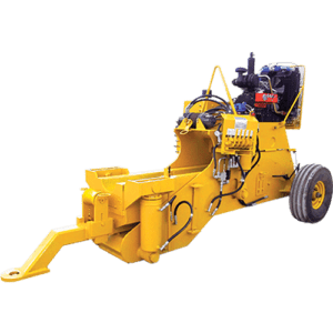
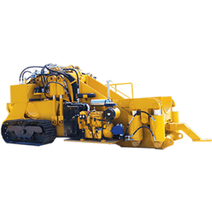
Super 36″ – 48″ Pipe Bending Machine

Super 36″ – 48″ Pipe Bending Machine Features
- Two Stage Pump
- T1 Steel Body Construction for long life & extra strength
- Calibrated Indicator Rod for precise repeatable bends
- Single operator control station for all functions
- PTFE sealing system in all cylinders
- Designed to bend all grades of API-5L pipe within its range
- Easily towed on the right of way by a suitable tractor
- Towing eye can be raised & lowered by actuating the Stiffback controls
- Hydraulic remote control valve system
- Bend pressure control at operator console
- OSHA Gate on operator station
- Large extra capacity filter
PRODUCT DETAILS
| BORE (IN) | STROKE (IN) | ROD (IN) | |
| InBoard Cylinder | 10 | 5 | 4.5 |
| OutBoard Cylinder | 14 | 18 | 9 |
| Pin Up Cylinder | 6 | 23 | 4 |
| Clamp Cylinder | |||
| Pump Type | Vane, Fix Volume | ||
| Pump Flow | 110 gpm | ||
| Valve | 5 Section | ||
| Filtration | 3 Micron, Pressure Line | ||
| Hydraulic System Max Operating Pressure | 2500 psig | ||
| Hydraulic Reservoir | 290 gal | 1096 L |
| Dia (in) | |
| Minimum | 36 |
| Maximum | 48 |
| Manufacturer | Quincy QR-390, Stand Alone |
| Drive Type | Deutz Engine |
| Pressure | 210 psig |
| Flow | 67.0 acfm @ 175 psig |
| Length | 32′-3″ | 9,830 mm |
| Width | 12′-6″ * | 3,810 mm |
| Height | 10′-10″ | 3,302 mm |
| Weight (lbs/kg) | 120,750 lbs | 54,886 kg |
| Track Size | 50 Ton |
* Actual width may vary.
| Manufacturer | Ramsey |
| Drive Type | Hydraulic Motor |
| Pulling Force | 20,000 lbf |
| Cable Diameter | .5625″ |
| Free Wheeling Drum |
| Perkins 1206F Tier 4F Diesel Engine | 250 | hp |
| Operating Speed | 2200 | rpm |
| Fuel Tank | 80 | gal |
- Caterpillar 7.1 Tier 4F Diesel Engine (Domestic or Export)
- Perkins 1206D Tier 3 Diesel Engine (Export Only)
- Hydraulic Air Compressor
- Hydraulic mandrel controls with five-section valve & 3/4″ access connections
- Working lights
- Cold weather operating kit (-40º) available
| NOMINAL PIPE O.D. | MAXIMUM WALL THICKNESS BY GRADE | RECOMMENDED BEND | ||||||||||||||
|---|---|---|---|---|---|---|---|---|---|---|---|---|---|---|---|---|
| IN/MM | X52 | X60 | X65 | X70 | X80 | X100 | DEGREE PER ARC FOOT | RADIUS FEET | MAXIMUM 40 FOOT JOINT | |||||||
• A cell marked with a (-) represents the ability to bend up to 2.00″ thick. For wall thickness greater than that, contact DMI.
• Figures above represent empirical data and are recommendation only. They do not constitute a warranty.
• All bends are based on the use of DMI mandrels and approved Die Sets.
• For heavy wall pipe special Die Sets may be required.
• Figures shown above are provided as “Average” and will vary depending on the following:
- Actual wall thickness of the pipe.
- Actual Yield Stress of the pipe.
- Skill of the Operators handling the Bending Machine and Mandrel.
- Origin and Quality of the pipe.
- Type of Die and Bending Set being used.
• Normal unbend tangent for PBM 6-20 is 5′
• Normal unbend tangent for PBM 16-30 is 6′
• Normal unbend tangent for PBM 22-36 is 6′
• Normal unbend tangent for PBM 32-42 is 7′
• Normal unbend tangent for PBM 48-60 is:
- 11′ for Stiffback end with pipe support
- 13′ for Stiffback end with NO pipe support
- 8′ for Pinup end with pipe support
- 9′ for Pinup end with NO pipe support
Disclaimer:
Technical information provided for this equipment regarding performance, specifications, dimension and weights can vary depending on final configuration of the equipment. Please contact DMI International for actual specifications at time of shipment.
DMI International does not accept responsibility for errors regarding the technical information, nor the consequences of any errors, nor the consequences to changes in the specifications contained herein. DMI International reserves the right to modify the equipment performance and specifications without notice.